
Now that the cube is done, I’m resurrecting an old project. I’ve finally got enough stuff out in the garage to prototype my way out of an aluminium box. You can read the original arm writeups over on Hackaday.io for more detail, but In a nutshell it’s a really big, really fast, really accurate polar plotter arm
The Project

I’ve been making drawings as a part of my professional life for the last 10 years or so. It takes a lot of work to make a drawing, and usually it gets sent to a shop floor where it’s followed to make a part, then it sits in a database. I thought given how much work goes into drawings and how cool they look, it might be interesting to be able to put them up on a big wall, whiteboard, blackboard or other surface so everyone can check it out, but in a medium that’s close to the original ( hand drawn drafting was a profession in itself for decades )
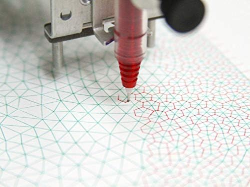
I was inspired by the Axidraw by Evil Mad Science Labs and plotter twitter to build a plotter to make this happen. I thought about a rectilinear arm for a bit, then a cable suspended one, but then realized the one thing I really wanted was a single mounting point, so it could easily be put up / taken down, as a long axis to mount would make it need to be more tailored to the room you’re putting it in, and cable suspended plotters require multiple mounting points, which is easy to screw up when moving from one place to another.
I landed on a polar plotting architecture for a number of reasons, it’s somewhat novel, only requires two axes, the machined parts can be small but the reach can be very large, it makes for cool looking art ( besides drawings ), as you can draw in rectangles or squares that fit in the circle, or do large circular plots, like a radar screen, planet, or even an orbital trajectory.

That’s where this project gets its name, Hermann Oberth was a german physicist and mentor to Wernher Von Braun (the guy who made Saturn V a reality). He did the math that lead to many rocketry firsts, and the Oberth effect and maneuver are named after him. The Oberth maneuver is simply to burn a rocket on a close flyby to a large gravitational body to gain extra velocity. His realization of this mathematically beneficial maneuver changed scientists impression that interplanetary travel was impractical, as much less fuel is needed when using gravitational bodies to assist.
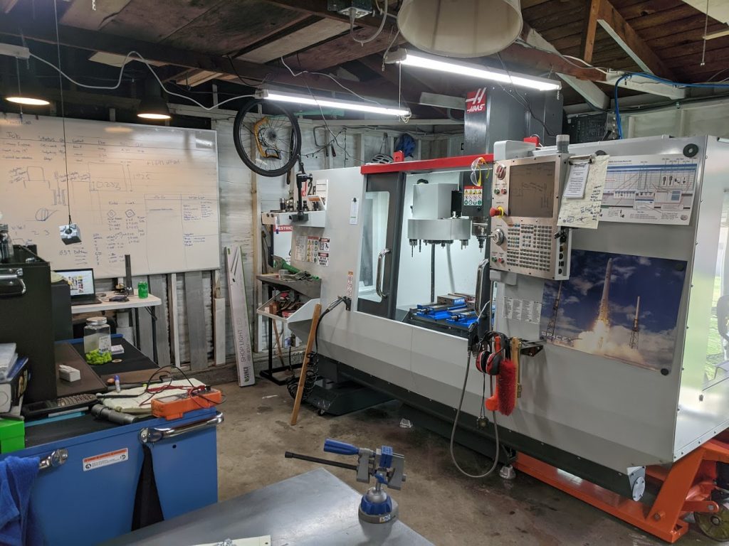
Now that I’ve got a machine shop with enough kit to make most of this myself, I’d like to eventually turn this into a product, geared towards artists, homeowners, or businesses that want mural art. Kind of like a high end kinetic sculpture / utility tool for making art. I want it to look real nice and be very performant, but still be reasonable to build and sell to a high end market. I figure if they are popular I’d sell max 100 a year, and I want the price point to land somewhere between $5,000 – $10,000 but for it to feel like a great value at that price.
The Process
The first couple things I did for this project were to research potential drive motors and gearboxes, frame the mechanics with a spreadsheet calculator, and generate some sketches of what the arm might look like. I first did this about two years ago, but then got busy with other projects and kind of left it there. Now that those are mostly done, I’m going to revisit everything with an eye to using the Haas to make components.
Some things I already got done:
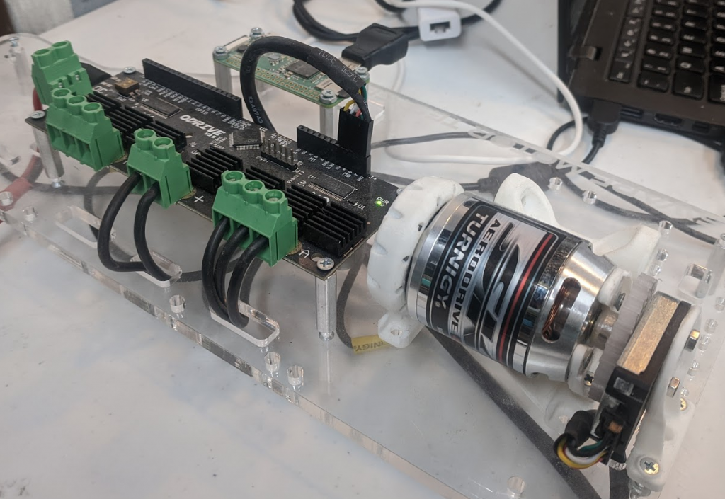
I picked the O-drive brushless DC motor driver as the motor driver, and after a recent discussion with an old colleague (Shane Colton, who has a great blog about electronics and cameras here ) I found a awesome magnetic encoder to use with it. I’m still thinking about which motor is best, at some point I’d like to design my own motor for it, and have it made (probably in Taiwan or similar). I’d also like to revisit the Odrive design and make a more compact single motor driver board from the same design, and put one on each axis.
Here’s an early test of the Odrive with an optical encoder. I fired it up again a couple weeks ago and got some more parts of its default code working, I was planning on adding some of my own encoder code, but it looks like since I’ve used it last it supports a bunch of other magnetic encoders (yay!).
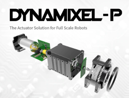
I decided on a cycloidal gear reduction after seeing Robotis’s implementation in their Pro Dynamixel servo motors and researching its features. Cycloidal reductions have the following benefits:
- Low cost
- Low backlash
- High(ish) reductions possible
- No sliding contact / less wear
- Non-backdriveable
- Can produce without a gear hobb ( made of cams and spline surfaces )
- Can prototype without grinding ( I hope ) .
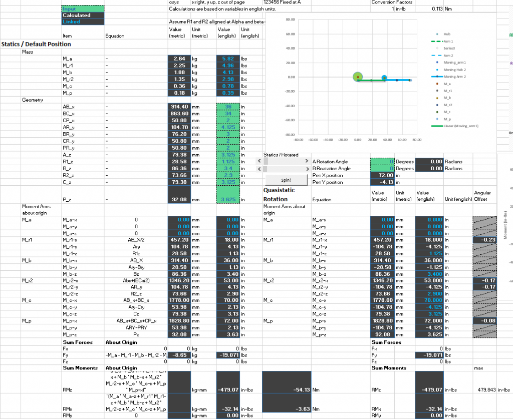
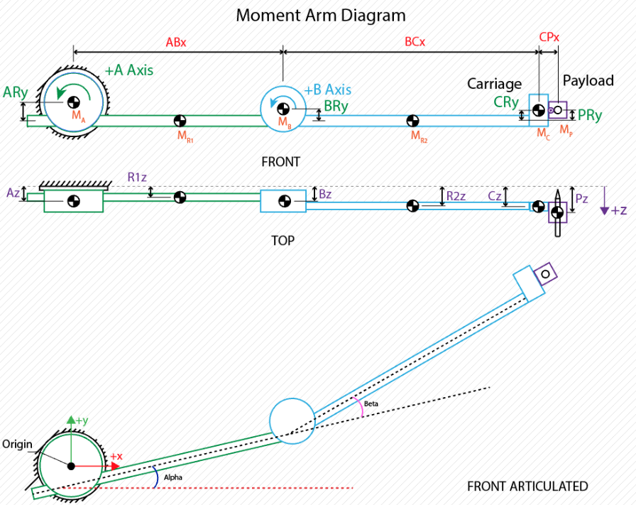
I made a spreadsheet calculator that does the following
- Calculates free body diagram forces and moments in arm / mounting location
- Has sliders for rotating each arm axis
- Allows changing length and mass of each arm segment / offsets of hubs.
- Approximation for dynamic load cases
- Cycloid Gear reduction calculations and spline points output for profile
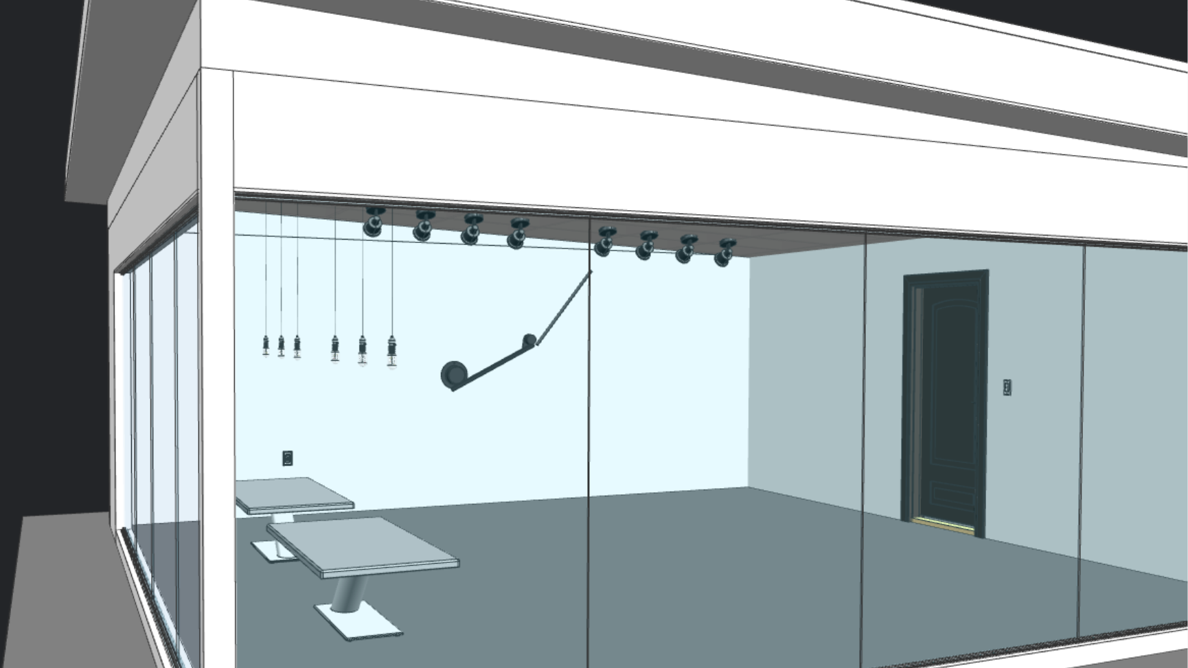
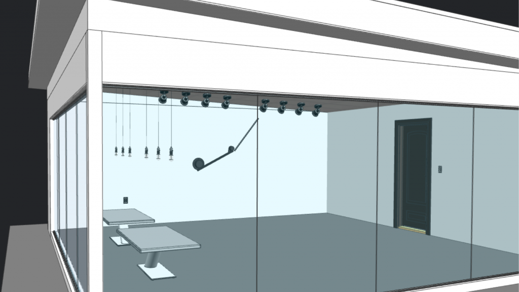
And here are some quick sketches of what the arm might look like.
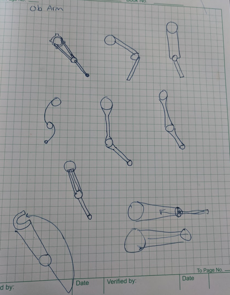
It’s super rough and I’m going to focus on mechanical layout and design next, starting with detailed design of the gearboxes, followed by the mount, arms, end effector, and finally the nonstructural covers.
Next Steps
I’m going to spend some time iterating on the gearbox and getting the odrive control working well. Once I know how big the gearboxes and motors will be, I’ll dive back into refining the concept and mechanically designing the arm.